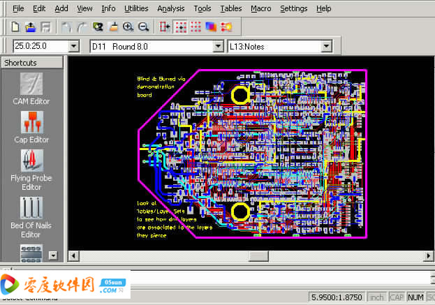


Then, according to the PC board type and the thickness of the copper foil on the substrate (Edit->Change->Dcode), check whether the offset of the circuit PAD is relative to the drill hole (if the PAD is biased, use Edit->Layers. Then check the minimum drilling hole size, the hole-to-hole (or slot) minimum spacing (Analysis->Check Drill), and the minimum distance between the hole edge and the routing edge (Info->Measure->Object-Object) Satisfy process capability.įirst, measure the minimum wire diameter and wire spacing (Analysis->DRC) to see if it meets the process capability. When the customer does not provide the drilling file, you can use the aperture hole to turn to Flash (Utilities-> Draw-> Custom, Utilities-> Draw-> Flash-> Interactive) and then turn to drill (Under drilling hole editing status, Utilities->Gerber to Drill) First import the file (File->Import->Autoimport) automatically, check whether the data is complete, align the layers (Edit->Layers->Align) and set the origin (Edit->Change->Origin ->Datum Coordinate), arrange the layers in a certain order (Edit->Layers->Reorder) and delete the unused layers (Edit->Layers->Reorder).


 0 kommentar(er)
